This is a cooler we made in our hostel room during summer season. This cooler is cost effective that it can be built under 1300rs
Hi Electronic enthusiasts! Welcome to the right place for sharing the knowledge in electronics and robotics. It is the place where anyone can share their knowledge and help others to make projects. Feel free to help others because it is said that the right knowledge can be obtained by learning and sharing. Hope this blog helps the people who are passion enough to learn small homemade projects and get benefited from them...
Thursday, September 22, 2016
PIR controlled electrical appliance
This PIR controlled electrical appliance is very useful to our home.It is so cheap to make...let's try it guys...its only 120rs
Wednesday, March 2, 2016
PROBLEM WITH YOUR DESKTOP COMPUTER NOT HAVING A SERIAL COM PORT HERE'S A SOLUTION WITHOUT USING A SERIAL TO USB CONVERTER
After i closed my CPU and connected the cables. I have googled about my mother board model. I got a circuit diagram showing headers like serial parallel etc with its pin configuration as shown below.
 |
| PHOTO SHOWING A 9PIN SERIAL HEADER |
 | |
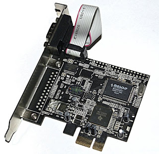
| SERIAL AND PARALLEL POTS ON PCI CARD |
 |
| CONNECT TX, RX AND GND PINS TO THE HEADERS |
 |
| THE SCREW DRIVER IS FOR POINTING THE HEADER |
The solution is that our mother boards has does not have a external COM PORT but has a internal COM PORT with serial headers consisting of 9 pins as labelled below. This is the serial port having named as COM1. You need top just identify whats the name of the pin like TX,RX,GND etc. connect the wires and take out of the CPU so that you can connect with the external peripherals like ZIGBEE, programming a micro controller,BLUETOOTH etc. with suitable voltage level converters like MAX232 etc or using a potential divider or a transistor based voltage converter.
 |
| THIS PHOTO SHOWS THE RX, TX AND GND PINS TAKEN OUT OF THE CPU |
Now I will show a small demo using TX, RX, GND pins.The serial port has different voltage levels for high and low bits completely different from the TTL logic where 0v is for low bit and 5v is for high bit. The voltage levels are in the range of +3 to +15 volts or the range −3 to −15 volts with respect to the ground/common pin; consequently, the range between −3 to +3 volts is not a valid RS-232 level.
 |
| THE VOLTAGE DIFFERENCE BETWEEN TX PIN AND GND IS NEARLY 12V |
This is the time for testing it. Here i have connected the TX wire and RX wire. What ever you transmit data it is sent via TX wire and received through RX wires as they are connected.
 |
| PHOTOS SHOWING THE TX AND RX WIRES CONNECTED TOGETHER |
Remember that you have to use COM1 as the serial port and the below photos shows how the data is transmitted and displayed on the XCTU window.
 |
| PHOTO SHOWING COOL TERM SOFTWARE |
 |
| SHOWING THE SELECTION OF COM PORT AND BAUD RATE |
 | |||
| THE BLUE LETTERS ARE CHARACTERS TYPED AND TRANSMITTED VIA TX AND THE RED CHARACTERS ARE THE ONES THAT THEY ARE RECEIVED THROUGH THE RX WIRE. |
This is for educational purpose only. Be careful when opening your CPU or ask a expert to to this. We are not responsible for any damage of you computer as they may contain static charges and without any prior precautions you may damage your CPU.
FEEL FREE TO POST YOUR QUERIES AND YOUR EXPERIENCES IN THE COMMENT BOX AS THEY MAY HELP OTHERS.
Subscribe to:
Comments (Atom)
.bmp)
.bmp)


