Feeling bored at my home the last sunday i decided to clean my desktop computer. I opened my CPU and began to clean it. When i was cleaning the mother board part i was wondered how the PCB is fabricated and what are the peripherals we can connect. I was examining each and every part of the mother board like where the RAM is placed ,HARD DISK etc. Suddenly my eyes got focus on the header consisting of nine pins and named it as serial and also there a header named as parallel.
After i closed my CPU and connected the cables. I have googled about my mother board model. I got a circuit diagram showing headers like serial parallel etc with its pin configuration as shown below.
 |
| PHOTO SHOWING A 9PIN SERIAL HEADER |
Some people uses PCI card that consists of a serial and a parallel port as shown below
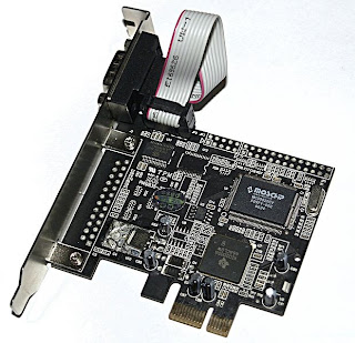 |
| SERIAL AND PARALLEL POTS ON PCI CARD |
|
I was amazed to see it was the serial COM port i was finding problems in to get it on my pc. It was known that the recent coming desktop does not have any serial ports because it was old and the USB has became the universal adoptable interface dominating the traditional serial port and parallel ports. So many buy converters like FTDI chips, SERIAL TO USB connectors etc. They cost a bit higher and some times they may not be available in your area.
 |
| CONNECT TX, RX AND GND PINS TO THE HEADERS |
 |
| THE SCREW DRIVER IS FOR POINTING THE HEADER |
The solution is that our mother boards has does not have a external COM PORT but has a internal COM PORT with serial headers consisting of 9 pins as labelled below. This is the serial port having named as COM1. You need top just identify whats the name of the pin like TX,RX,GND etc. connect the wires and take out of the CPU so that you can connect with the external peripherals like ZIGBEE, programming a micro controller,BLUETOOTH etc. with suitable voltage level converters like MAX232 etc or using a potential divider or a transistor based voltage converter.
 |
| THIS PHOTO SHOWS THE RX, TX AND GND PINS TAKEN OUT OF THE CPU |
Now I will show a small demo using TX, RX, GND pins.The serial port has different voltage levels for high and low bits completely different from the TTL logic where 0v is for low bit and 5v is for high bit. The voltage levels are in the range of +3 to +15 volts or the range −3 to −15 volts with
respect to the ground/common pin; consequently, the range between −3 to
+3 volts is not a valid RS-232 level.
 |
| THE VOLTAGE DIFFERENCE BETWEEN TX PIN AND GND IS NEARLY 12V |
This is the time for testing it. Here i have connected the TX wire and RX wire. What ever you transmit data it is sent via TX wire and received through RX wires as they are connected.
 |
| PHOTOS SHOWING THE TX AND RX WIRES CONNECTED TOGETHER |
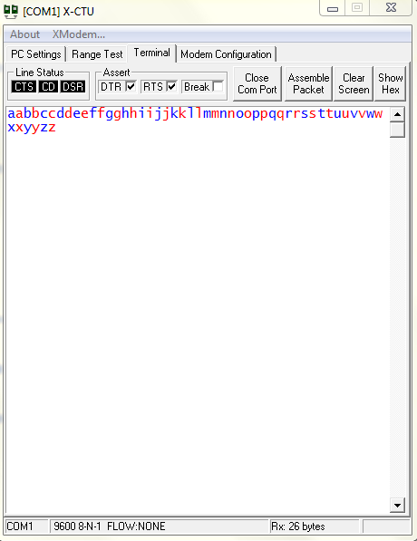
To check it open any serial terminal software like hyper terminal. Hyper terminal is present in windowsXP so windows7 or above users can use software's like cool term, tera term, XCTU etc.Here i used a XCTU software from DIGI. more details on XCTU software is given in one of my posts
http://letslearnandcreate.blogspot.in/2013/06/configuring-xbee-series-2-modules-part-1.html
Remember that you have to use COM1 as the serial port and the below photos shows how the data is transmitted and displayed on the XCTU window.
 |
| PHOTO SHOWING COOL TERM SOFTWARE |
 |
| SHOWING THE SELECTION OF COM PORT AND BAUD RATE |
 |
| THE BLUE LETTERS ARE CHARACTERS TYPED AND TRANSMITTED VIA TX AND THE RED CHARACTERS ARE THE ONES THAT THEY ARE RECEIVED THROUGH THE RX WIRE. |
|
|
|
This is for educational purpose only. Be careful when opening your CPU or ask a expert to to this. We are not responsible for any damage of you computer as they may contain static charges and without any prior precautions you may damage your CPU.
FEEL FREE TO POST YOUR QUERIES AND YOUR EXPERIENCES IN THE COMMENT BOX AS THEY MAY HELP OTHERS.
.bmp)

.bmp)