Monday, September 16, 2013

List of robotics and electronics shops in india


 http://www.vegarobokit.com/

http://www.robokits.co.in/shop/

http://www.probots.co.in/

http://www.rhydolabz.com

http://kitsnspares.com/user1/buyproduct.asp

http://www.nex-robotics.com/

http://www.protocentral.com/

http://store.extremeelectronics.co.in/

http://www.bhashatech.com/

http://www.onlinetps.com/shop/

http://www.robosoftsystems.co.in/

http://www.vegakitindia.com/

 http://www.sunrom.com/

http://in.element14.com/

http://www.nskelectronics.com/home.html

http://www.makemyhobby.com/

http://www.simplelabs.co.in/

http://in.mouser.com/

http://www.technido.com/store/

http://www.arelab.org/

http://edubotix.in/roboshop.html

http://tenettech.com/

http://www.ventor.co.in/

http://www.digibay.in/

http://www.robosoftsystems.co.in/roboshop/index.php/

http://www.mgsuperlabs.co.in/estore/

http://discovertechcom.com/

http://www.deccanrobots.com/

http://www.rcdhamaka.com/

http://www.intlabz.com/

http://www.embeddedmarket.com

http://www.thinklabs.in/

http://www.digikey.in/

http://www.technophilia.co.in/

http://products.li2.in/

http://www.robomart.com/

http://www.utsource.net/

http://www.thinnkware.com/webshop_page/

http://www.metalmate.in/index.htm

http://www.campuscomponent.com/

http://shop.sumeetinstruments.com/

http://www.technologyahead.com/

http://www.idasystems.net/

http://www.sproboticworks.com/


      These are for only educative purpose only. We don't have any contacts with the above stores
and we are not paid  for that. Before buying please check the reviews of the products and we are not responsible for the products they sell.

IF YOU KNOW MORE STORES THEN PLEASE WRITE IN THE COMMENTS. THIS MAY BE HELPFUL TO OTHERS AND WILL BE APPRECIATED.

Best websites for new budding electronic enthusiasts


  1. http://www.technologystudent.com/elec1/elecex.htm
  2. www.instructables.com
  3. http://homemadecircuitsandschematics.blogspot.in
  4. http://www.engineersgarage.com/
  5. http://www.circuitstoday.com/
  6. http://www.electronicsforu.com
  7. http://www.electroschematics.com/ 
  8. http://electronicsproject.org/ 
  9. http://www.diy-electronic-projects.com/ 
  10. http://www.electronics-lab.com/projects/ 
  11. http://circuiteasy.com/ 
  12. http://www.eleccircuit.com/ 
  13. http://www.circuit-projects.com/ 
  14. http://www.edgefxkits.in/ 
  15. http://www.buildcircuit.com/ 
  16. http://www.coolcircuit.com/ 
  17. http://www.electro-tech-online.com/ 
  18. http://www.aaroncake.net/circuits/ 
  19. http://www.edaboard.com 
  20. http://www.circuit-projects.com/robotics/ 
  21. http://letsmakerobots.com 
  22. http://www.societyofrobots.com/ 
  23. http://www.botskool.com/ 
  24. http://101science.com/robots.htm 
  25. http://www.robotroom.com/ 
  26.  http://www.robotbasic.org/10.html
  27. http://blog.vinu.co.in/ 
  28. http://extremeelectronics.co.in/ 
  29. http://www.ladyada.net 
  30. http://pinterest.com/pdavislibrarian/electronics-projects-for-kids/ 


    These are for only educative purpose only. We don't have any contacts with the above websites
and we are not paid  for that.


IF YOU KNOW MORE WEBSITES THEN PLEASE WRITE IN THE COMMENTS. THIS MAY BE HELPFUL TO OTHERS AND WILL BE APPRECIATED.

Water Level Indicator/Rain Sensor

There is always a problem in our home whenever we switch on the motor to fill the tank with water. So, we have decided to solve the problem by making a circuit which senses the rain/water


Rain Alarm: This circuit is built around just two transistors as the main active components so as to warn about the rain. Also the same circuit can be used as water level indicator by arranging the sensor at the top of the tank.
Operation: The configuration is in the form of a standard Darlington pair, which increases its current amplification capacity hugely. Rain drops or water drops falling and bridging the base with the positive supply is enough to trigger the alarm. The purpose of Resistor and Capacitor is to insert some delay so that the transistor is on for some time (R*C=2.2mS) and so the Piezo Buzzer starts ringing. The whole circuit is given 9V D.C power supply.


Sunday, June 23, 2013

CONFIGURING THE XBEE SERIES-2 MODULES PART-1


                                                    Today I will show how to set up xbee series_2 modules. After that we will see a small chat application using these series_2 modules.In this tutorial we will see a basic point to point communication.

PARTS YOU NEED:

1.XBEE SERIES_2 MODULES -2no.
2.XBEE USB EXPLORER BOARD  (If your computer has a serial port you can use a serial cable instead)
3.USB CABLE IF USB EXPLORER BOARD IS USED
4.X-CTU SOFTWARE    (You can download here)

         X-CTU software has four tabs like pc settings, range test, terminal, modem configuration as shown below.

                       For the usb board to be connected to your computer you need FTDI drivers. because the usb board has a FTDI chip. It is a usb to serial converter which opens a virtual com port. So you need these drivers. (you can download here).
   
                      After you install these drivers in your computer you can connect your usb board with your xbee plugged in. Now a virtual com port is created with a name like COM2,COM3 etc as it differs from one computer to other. You can see it in your control panel(device manager). I will not discuss it as it is out of scope here. (If you feel any doubts post in the comments section)

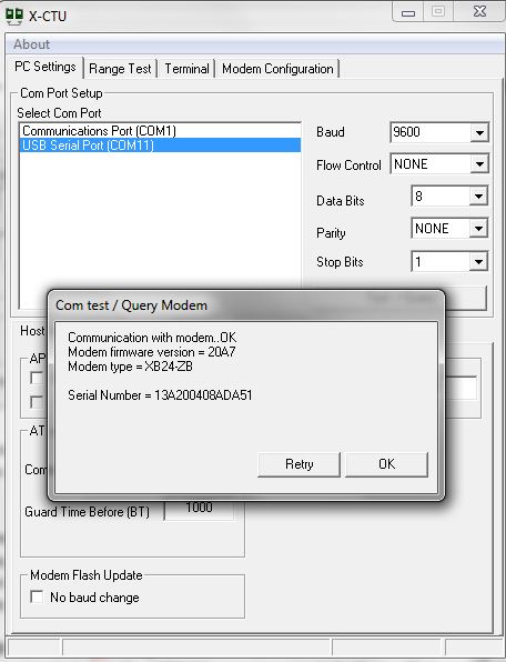
                     Now open the X-CTU software. In the pc settings you can see different COM PORTS as shown in the above figure. My usb board opens port named as COM11 as you can see in the figure. Click on your corresponding port and keep the baud rate, flow control etc as shown as shown in the figure.I configured my xbee to communicate with a baud rate of 9600. After you set these settings click on the Test/Query button. Now you can see a pop up as shown below.

                           You can see the firmware version, modem type and the serial number. Then click ok. Now your XBEE is connected and ready to be configured. Don't confuse yourself thinking about the firmware version, modem type, serial number. You need to configure one XBEE as a coordinator radio and the other as a router. To avoid confusing write "C" for coordinator and "R" for router on a piece of paper and attach to the the XBEE radios. Take the radio which is named as coordinator and place it on to the usb board. Now this is to be configured as coordinator.

                       In the X-CTU software click on the Modem Configuration tab. You will see a window like this screenshot as shown below.

                                       Now click the READ button. You can see your XBEE radio firmware version and function set and all other options which we will configure now. As my XBEE radio is previously as a coordinator my settings look like this.


                                   You can see a option like Modem XBEE. It is a type of the modem you purchased. It can be seen on the backside of your modem or this is can be known in the X-CTU software itself when you click on the Test/Query button in the pc settings tab as we done it before. You can select your XBEE Modem type (here it is not necessary as we already click the READ button). (If you select the any other modem type than your XBEE Modem type it will not work and you can brick your XBEE modem. Bricking the XBEE will be posted if you want it. Those  who want just request in the comments section).


                       In the part-2 you will see how to setup the XBEE radio as a coordinator or a router.


                                                                                                                  CONTINUE TO PART-2